Guide to Selection of Protection Systems
Guide to Selection of protection systems, of which the current transformers constitute a vital part, can be complex. Our suggested rating for these applications should be treated with caution as they may be subjected to variations due to relay characteristics or to components of the scheme. Relay manufacturer's recommendation should be followed.
General Type of Relay
Protection System
Typical C.T. Requirement
Burden (VA)
Class
Accuracy Limit Factor (ALF)
Magnetic Trips
Overcurrent
2.5 - 5
10P
5
Magnetic O/L with dashspot
Motor overcurrent with time relay
5
10P
5 - 10
Some low consumption thermal types
Motor overcurrent with time relay
2.5
10P
10 to 15
Thermal
Motor overcurrent with time delay
7.5
10P
10 to 15
Inverse Definite Min. Time relays (I.D.M.T.)
Overcurrent
15
10P
10 to 15
I.D.M.T. Earth Fault Relay
Unrestricted earth fault with approx. time grading
15
10P
10
I.D.M.T. Earth Fault Relays
Unrestricted earth fault where phase fault stability or accurate time grading required
15
5P
10
Burden Guide for Measuring Instrument
VA
Instrument
0.5
Short scale moving iron ammeters
0.75 to 1.5
240o scale moving iron ammeters
0.1 to 1
Rectified moving iron ammeters
1 to 1.25
Watt/VAr/phase angle meters
2 to 4
Recording ammeters
2 to 3.5
Maximum Demand Indicators
3 to 3.5
Combined MDI & MI ammeters
0.5 to 4
Paladin transducer
0.5 to 4
Protector modules
5 to 10
Electronic control system
Application
Class of Accuracy
As a standard for testing other current transformers
Better than 0.1
Precision testing
0.1
Precision metering
0.1 or 0.2
Tarif metering (bulk supplies)
0.2
Tarif metering (general), transducers, test equipment, control systems
0.5
Watt/VAr/Phase Angle meters, recording meters, protection devices
1
Industrial ammeters, maximum demand indicators
1 to 3
Approximate measurements
5
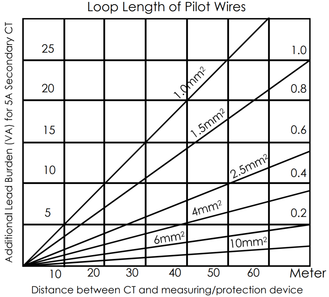
Secondary Lead Burden
The impedance of the pilot wire between the CT and Relay/Instrument will add to the total burden of the measurement of protection circuit. The impedance and hence burden can be significant for long pilot wire run and must be taken into account. This is particularly critical for class 'X' CTs. It may be advisable to use 1A secondary for extremely long pilot wire run. The chart shows the approximate additional burden that must be added to the total CT burden for various sizes of pilot wires at varying distances.